
Ballbar testing
We measure the circular motion accuracy of your machine tool with a Renishaw QC20-W ballbar and reveal backlash, servo mismatch, squareness and circularity errors in a single test. We report the result to ISO 230-4.
What is a ballbar test
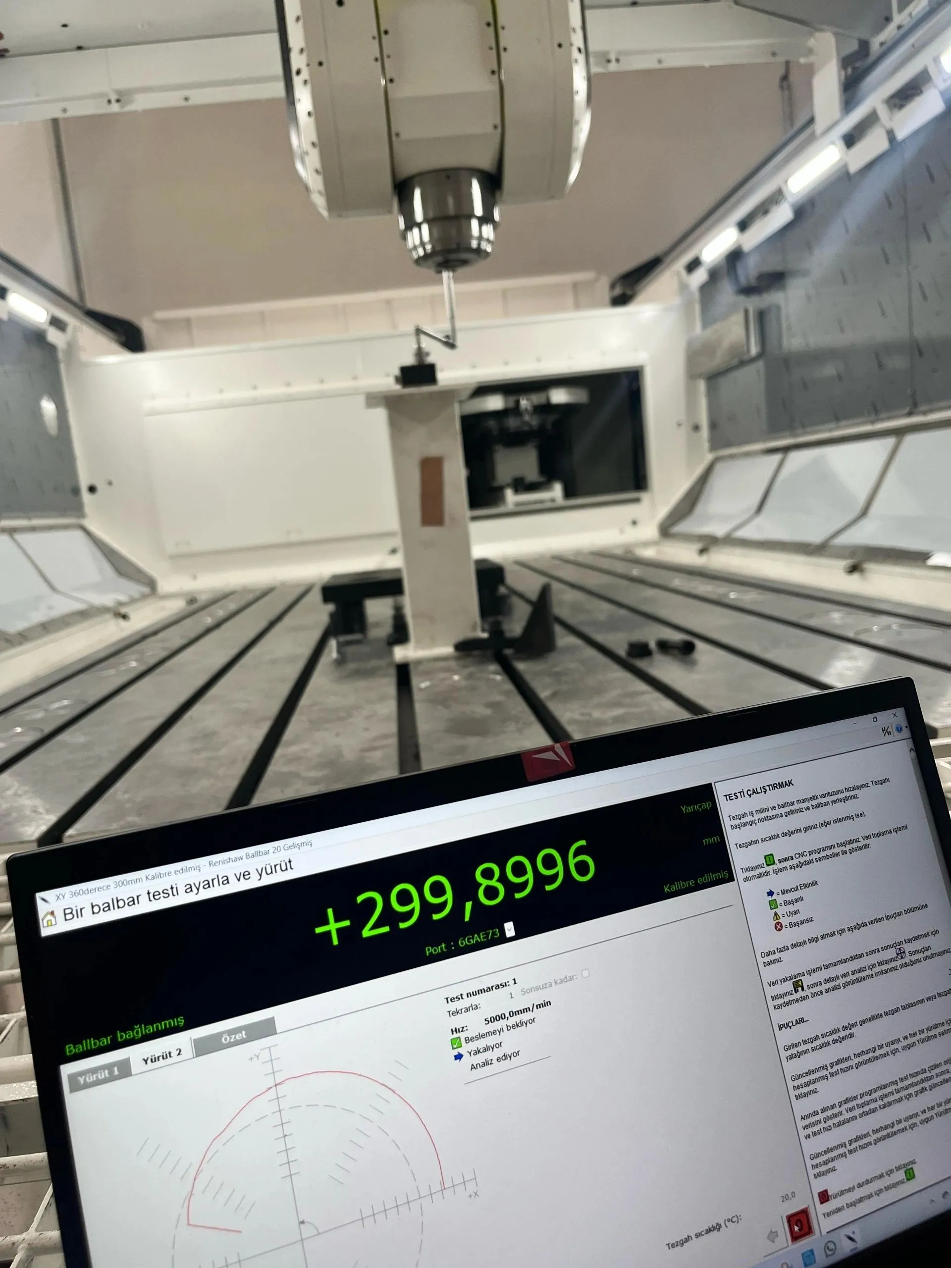
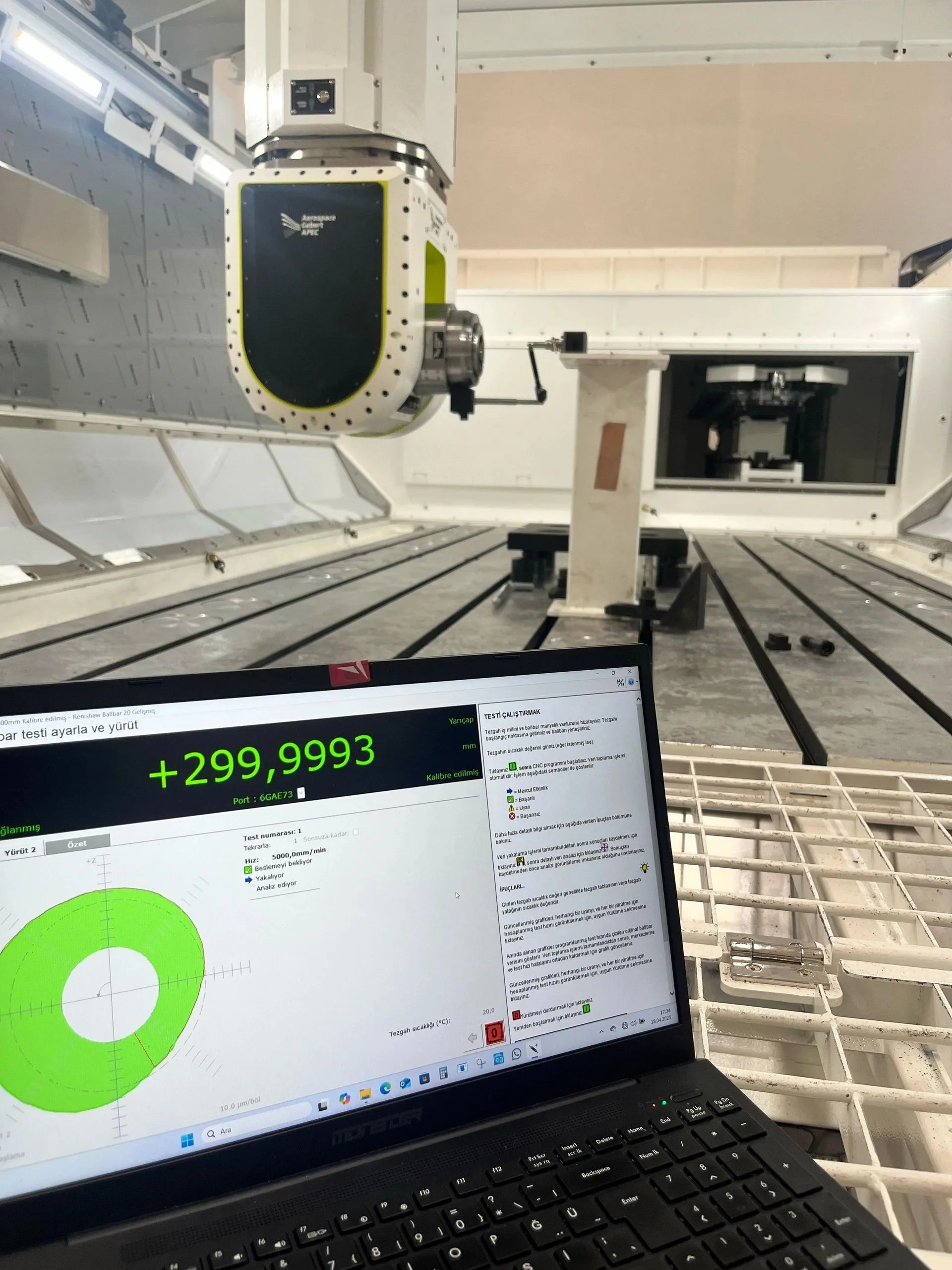
The ballbar is a precision measuring bar mounted between the spindle and the table. Running a special program, the machine moves its axes together along a circular path; meanwhile the instrument measures the smallest change in radius.
This shows in a single plot how two axes work together, that is, their interpolation capability and servo performance. A diagnosis that takes a long time with conventional methods is done quickly with a ballbar, without taking much time away from production.
What the plot shows
ISO 230-4
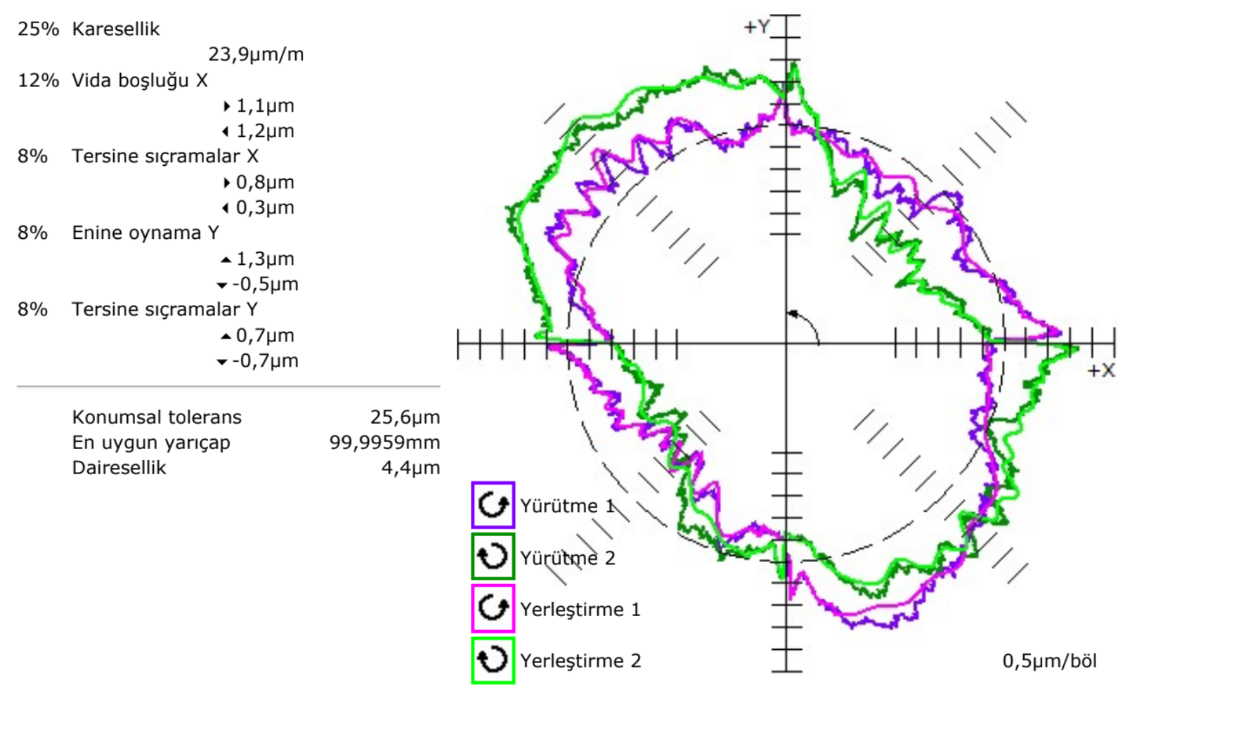
The test software analyses the measured trace and separates the errors by type. The values in the last column come from the real measurement shown in the plot at the top of this page. We explain how to read the plot step by step in our article How to read a ballbar plot.
| Error | How it shows in the plot | Sample measurement |
|---|---|---|
| Circularity | The largest deviation of the measured trace from an ideal circle; the combined effect of all errors. | 4.4 µm |
| Squareness | The two axes are not exactly perpendicular; an oval tilted at 45°. | 23.9 µm/m |
| Backlash | Mechanical play when the axis reverses; a step on the axis. | X 1.1 / 1.2 µm |
| Reversal spikes | Delay of the servo system at the moment of reversal; a spike on the axis. | X 0.8 / 0.3 µm |
| Lateral play | Play in the guideways; a shift added to the trace when the direction changes. | Y 1.3 / −0.5 µm |
| Servo mismatch | The two axes respond differently; the traces in the two directions form ovals tilted relative to each other. | — |
How the test is done
Set-up
The ballbar is placed between the spindle and the table in magnetic cups.
Circular motion
Running the test program, the machine draws a circle in the selected plane, clockwise and anticlockwise.
Analysis
The software analyses the measured trace and calculates the value of each error type and its contribution to the total error.
Report
The plot, the values and recommendations go into the report. If needed, laser calibration follows.
Why it matters
| It shows the accuracy of the machine quickly and reliably. |
| It provides data for fault diagnosis and preventive maintenance planning. |
| It reveals mismatches in servo and mechanical components at an early stage. |
| It protects part quality and prevents unnecessary downtime. |
The ballbar test is used as a first diagnosis before laser calibration and for verification afterwards. When it should be repeated is explained on the laser calibration page.
Frequently asked
What is a ballbar test?
The ballbar is mounted between the spindle and the table and measures the change in radius while the machine moves in a circle. Backlash, servo mismatch and circularity error are read from the plot. We use a Renishaw QC20-W.
What is the difference between the two?
The ballbar shows the general condition of the machine in a short time. The laser measures the position error of each axis and makes correction possible. On our jobs we run the ballbar first, then the laser.
How often should it be done?
For a machine with no problems we recommend every six months. Repeat the measurement after a tool crash or after replacing a ball screw, guideway, servo motor or spindle bearings.
Which machines do you measure?
Calibration is brand-independent: vertical and horizontal machining centres, bridge-type machines, lathes, deep-hole drilling machines, EDM and CMM.